EOAT signal boxes & I/O accessories
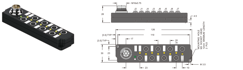
JB8M8-M16 8-port M8 junction boxes
8-port M8 junction box with PNP/NPN variants, IP67 protection, 10–30 VDC supply and LED indication.
Series image shown. Confirm the exact configuration against the model data below.
Price and lead time: confirmed on inquiry.
Technical specifications
Electrical and mechanical specifications
| Parameter | Value |
|---|---|
| Housing | Black nylon |
| Coupling nut | Nickel-plated brass |
| Contact carrier | Black TPU |
| Contacts | Gold-plated brass |
| Protection rating | IP67 |
| Operating voltage | 10–30 VDC |
| Current per port | 2 A |
| Total current | 6 A |
| LED current | 10 mA |
| Operating temperature | −30 to +80 °C |
| M8 ports | 8 |
| Signals per port | 1 |
| Signal indication | LED |
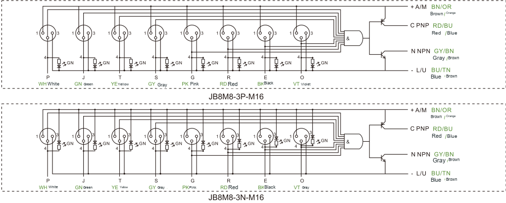
| Overall dimensions | 126 × 30 × 28 mm |
| Main connection | M16 × 0.75 |
| Mounting holes | 2 × Ø3.5 mm |
| Mounting screws | M3 socket head, minimum length 12 mm |
Available models
| Model | Output type | Weight |
|---|---|---|
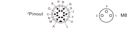
| JB8M8-3P-M16 | PNP | 120 g |
| JB8M8-3N-M16 | NPN | 120 g |
Compatible connectors
| Model | Configuration |
|---|---|
| JM8-M03T | 3-pin M8 straight field-wireable connector |
| JM8-M03L | 3-pin M8 angled field-wireable connector |
| JDNLK14-14-2M/P00 | 14-pin M16 molded cable, 2 m |
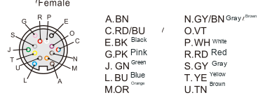
Pin and wire assignments
| Pin | Code | Wire color |
|---|---|---|
| A | BN | Brown |
| C | RD/BU | Red/blue |
| E | BK | Black |
| G | PK | Pink |
| J | GN | Green |
| L | BU | Blue |
| M | OR | Orange |
| N | GY/BN | Gray/brown |
| O | VT | Violet |
| P | WH | White |
| R | RD | Red |
| S | GY | Gray |
| T | YE | Yellow |
| U | TN | Brown |
ENGINEERING RESOURCES
Technical drawings
Inspect mounting holes, dimensions and interfaces. Open a drawing to zoom in or download the image.
Enlarge drawing ↗JB8M8-M16 · Dimensions
 Enlarge drawing ↗
Connection and installation details
 Enlarge drawing ↗
Connection and installation details
 Enlarge drawing ↗
Connection and installation details
Application details for your quotation
Match the sensor output type and supply voltage to the intended controller. Use the electrical limits in the table and confirm the final wiring configuration before integration.
Read the selection guide ↗